support@comsol.com
Corrosion Module Updates
For users of the Corrosion Module, COMSOL Multiphysics® version 6.2 provides new features to better define cathodic protection of pipelines, as well as the ability to include contact resistance on various boundary conditions. Learn about these updates below.New Point Nodes for Improved Corrosion Protection Modeling
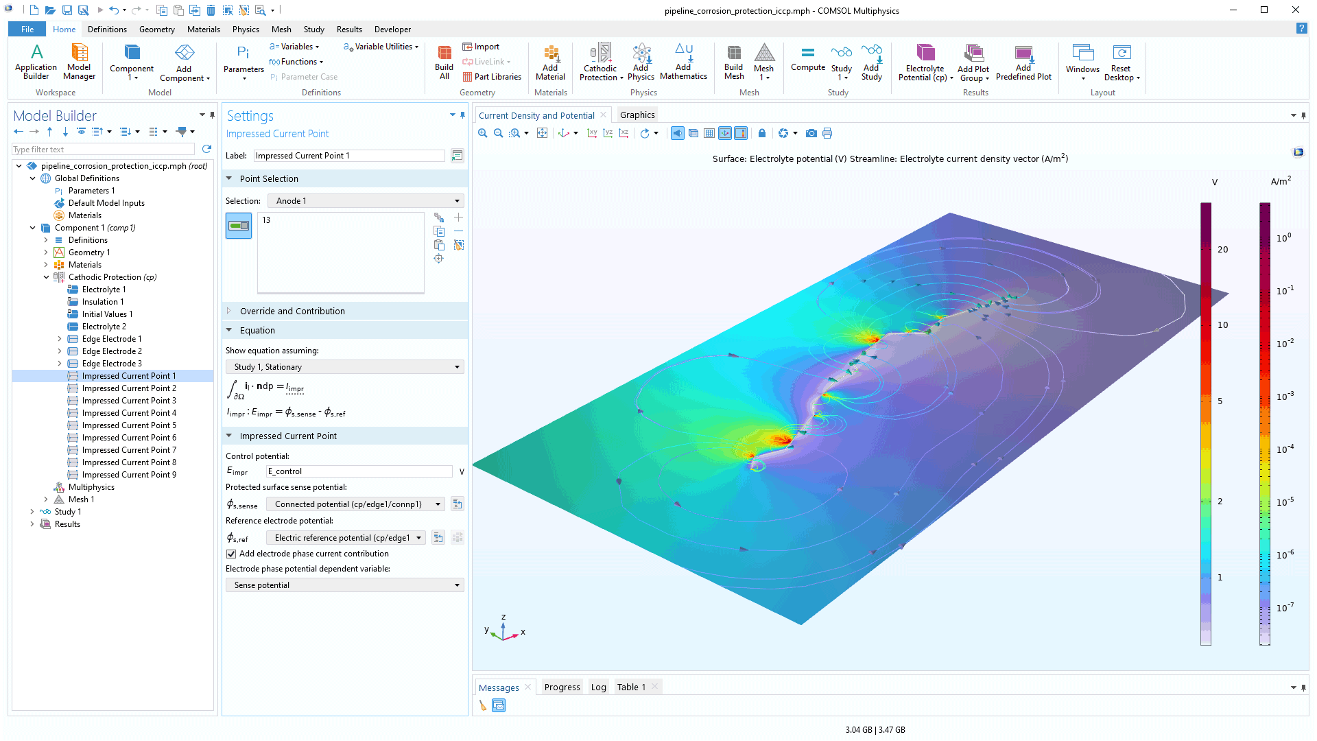
Several new features have been added to extend the ability to define models for the cathodic protection of pipelines and rails. A new Impressed Current Point feature is available to add to an electrolyte domain to define the location of the active electrode of an impressed current protection system. This feature is typically used together with the existing Connection Point feature for setting up a local impressed cathodic current protection system.
The Connection Point feature, available as a subnode to an Edge Electrode or Sacrificial Edge Anode feature, has been updated with a Define reference electrode check box that makes it possible to set a reference electrode potential at the same location. The reference electrode potential can typically be used by an Impressed Current Point feature to actively control the electrode potential at the location of the Connection Point.
Additionally, there is a new Sacrificial Point Anode feature that can be added at any point in an electrolyte domain to define a sacrificial anode, and a new External Short subnode to the Edge Electrode feature offers more flexible connection options between various points in a model. View these updates in the new Pipeline Corrosion Protection Using Impressed Current Cathodic Protection tutorial model.
Contact Resistance
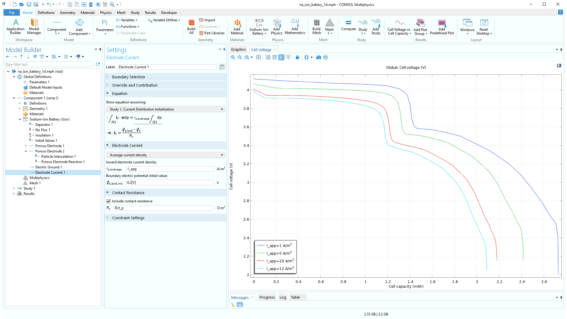
For the electrochemistry interfaces, external contact resistances can now be included for the Electric Ground, Electric Potential, and Electrode Current boundary conditions. This functionality can be enabled by the Include contact resistance check box in the Settings window, and the desired resistance can also be specified in the text field.
New and Updated Tutorial Models
COMSOL Multiphysics® version 6.2 brings several new and updated tutorial models to the Corrosion Module.
Pipeline Corrosion Protection Using Impressed Current Cathodic Protection
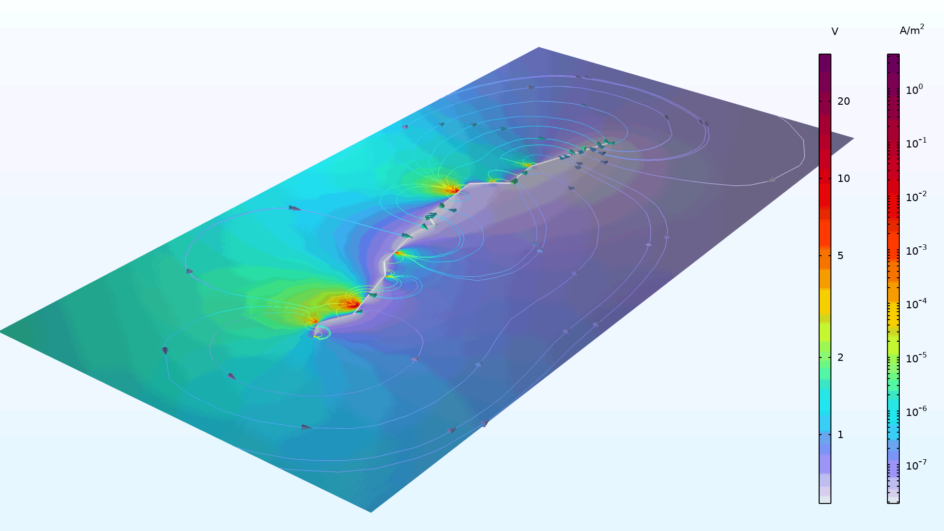
Application Library Title:
pipeline_corrosion_protection_iccp
Download from the Application Gallery
Corrosion Under an Evans Droplet
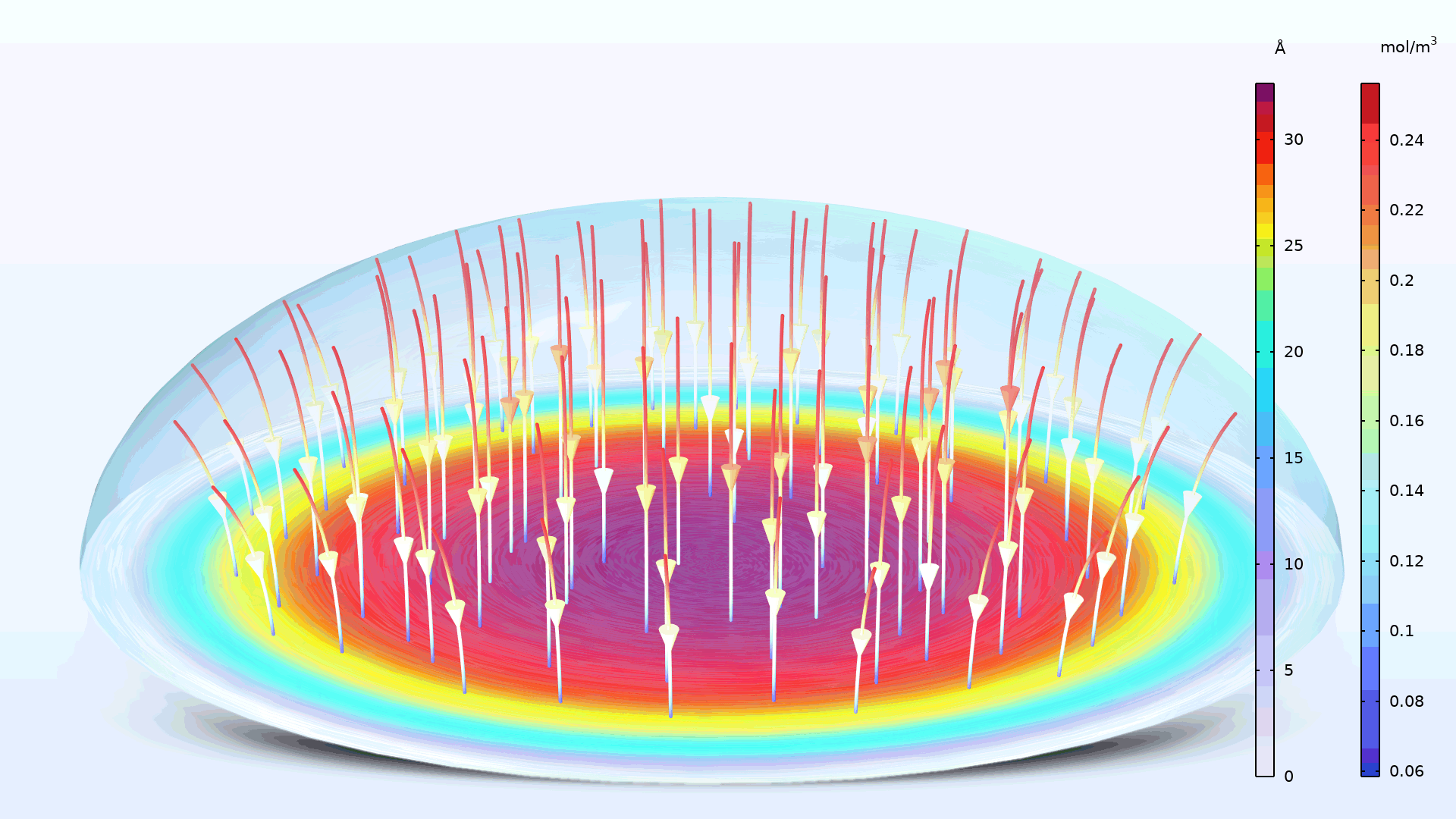
Application Library Title:
evans_droplet
Download from the Application Gallery