

One way to design utility boilers with high thermal efficiency is to improve their furnaces — the most important part in their energy conversion process. Studying furnaces in utility boilers requires engineers to account for radiation, which can be difficult to solve for analytically and expensive to study experimentally. As an alternative, we can use the COMSOL Multiphysics® software to analyze radiative heat transfer in utility boiler furnaces and improve their designs.
Investigating Furnace Radiation to Improve Utility Boiler Designs
When designing power plant and other utility boilers, it’s important to find ways of increasing their lifetime and thermal efficiency while decreasing their pollutant emissions. Optimizing the performance of large power plant boilers, for instance, is a common area of study. Today, we focus on one boiler design element in particular: the furnace. Within a furnace, chemical energy is converted into heat energy, which greatly affects the energy conversion process and thus the boiler’s thermal efficiency.
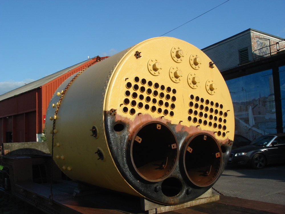
A retired scotch marine boiler with two coal-burning furnaces. Image by Andy Dingley — Own work. Licensed under CC BY-SA 3.0, via Wikimedia Commons.
Radiation is the key heat transfer mechanism in boilers. Thus, radiation behavior, such as the radiative heat flux on the combustion chamber’s furnace walls, must be accurately accounted for when studying these devices. Radiation is difficult to predict, and its complexity and dependence on the enclosure geometry means that analytical solutions exist only for very simple problems. Further, experimental modeling of furnace enclosures is expensive.
As an alternative, engineers can build numerical models to properly analyze such enclosures and evaluate thermal efficiency. In the next section, we go over an example model designed for studying radiative heat transfer in a utility boiler’s furnace.
Modeling a Utility Boiler to Evaluate Radiative Heat Transfer
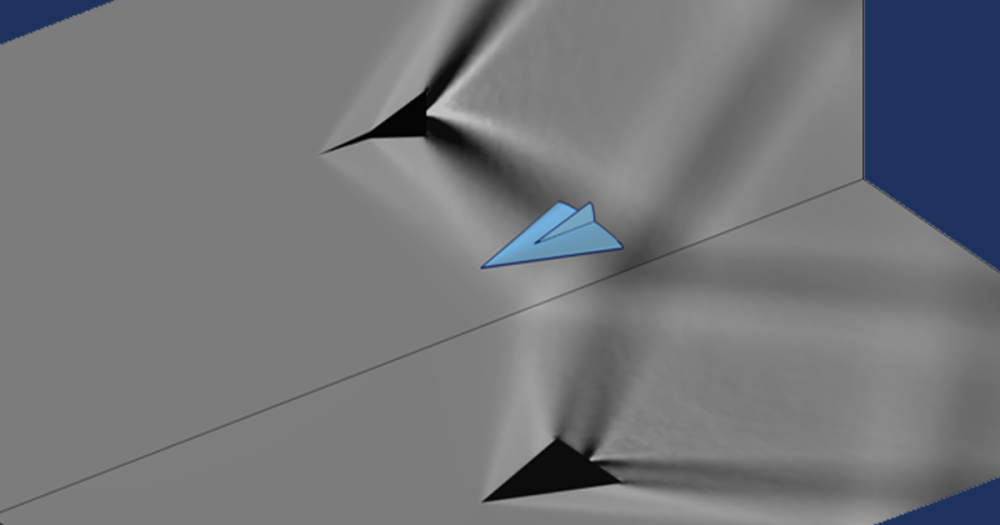
Let’s take a look inside our utility boiler model, which contains five very thin obstructions. This is a practical choice, as utility boilers often include thin obstacles, like panels, hanging in the radiation chambers. For our simulation, we model the obstructions as baffles with zero thickness to reduce the mesh and computational cost. The obstacles each contain an emitting-absorbing medium. Surrounding these baffles, which represent superheater panels, is a 3D enclosure that acts as the utility boiler’s combustion chamber and furnace walls.
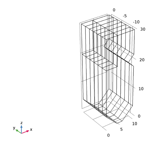
The obstructions in the utility boiler model.
For our assumptions, we draw from existing research by P.J. Coelho, J.M. Goncalves, and M.G. Carvalho, titled “Modelling of Radiative Heat Transfer in Enclosures with Obstacles” (Ref. 1 in the model documentation). The model’s main assumption is to use existing temperatures and properties, as seen in the table below, inside both the volume and surface zones.
| Coordinate (M) | Absorption Coefficient (1/M) | Temperature (K) |
|---|---|---|
| z ≤ 5 | 0.20 | 1600 |
| 5 < z ≤ 10 | 0.25 | 2000 |
| 10 < z ≤ 20 | 0.20 | 1600 |
| 20 < z ≤ 30 | 0.18 | 1200 |
As for solving our model, we use the discrete-ordinates method (DOM). This method is well suited for cases that involve radiation absorption and scattering in a cavity with a moderate optical thickness. We use the S4 DOM to calculate the distribution of incident radiation in the furnace and heat flux on the enclosure’s side walls. We end up with a set of 24 discrete directions that represents radiative intensity transport.
For more details on how we set up this model, including our use of the radiative transfer equation (RTE), boundary conditions, and the different quantities used in the model, refer to the model documentation.
Predicting Temperature and Heat Flux in the Furnace
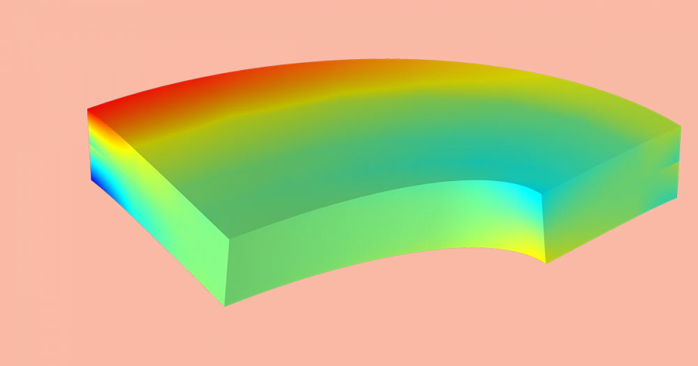
Using the model presented here, we can easily find the radiative heat flux behavior both inside the furnace and on its surfaces as well as compute the radiative intensity in the participating media. As we can see in the images below, the largest amount of incident radiation happens when the medium’s temperature and absorbing coefficient are at their highest point (the boiler’s burner level).
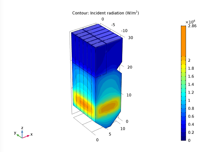
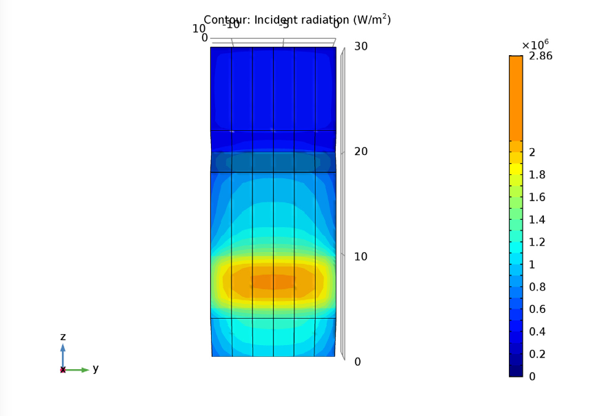
Incident radiation in a boiler (left) and on the front of a boiler (right).
Further, we can compare our results to those from the reference for various configurations. For example, the simulation below, which analyzes the predicted outgoing heat flux, is in good agreement with the published data. This helps confirm the validity of our simulation analysis.
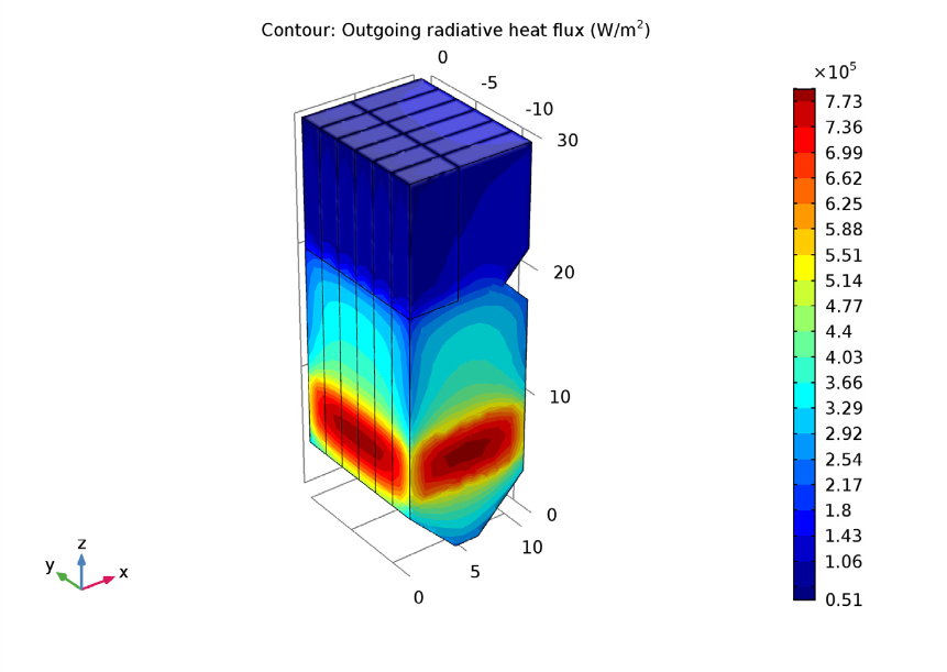
The outgoing heat flux on the boiler walls.
Learn More About Analyzing Radiative Heat Transfer in COMSOL Multiphysics®
- Browse through these blog posts on modeling heat transfer:
- See how to simulate radiation with COMSOL Multiphysics in this archived webinar

Comments (1)
mona aghaee
January 29, 2018Hi,
I have problem modeling radiation heat transfer in a slab. A constant radiation hits an slab and part of that id transferred through the slab, part is absorbed within the slab and part is reflected. How should I model this? There are a lot of complicated models answered but none of them works for this. where and how could i enter transmisivity and reflectivity of the slab? Could you please give some information?
Thanks
Mona