

Gears are devices that are widely used for the transmission of rotary motion from one shaft to another. Automobiles, electric motors, wind turbines, and other machines all require a gearbox in order to change their speed or torque. With the latest version of COMSOL Multiphysics® — version 5.2a — we bring you new gear modeling features and functionality, from components in the Parts Library to an array of tutorial models that illustrate potential applications.
The Fundamental Dynamics of Gears
Let’s begin with a simple definition. A gear is a rotating machine part that is comprised of a set of toothed wheels, with the purpose of transmitting power from one part of a machine to another.
Model of a gear.
Gears can be connected to one another and they can also vary in size. Transferring power from one gear to another gear enables you to do one of the following things:
- Increase the speed: Say you are connecting two gears to one another, with the first gear featuring more teeth than the second gear. If this is the case, the second gear needs to turn faster than the first gear. As a result, the torque in the second gear decreases, keeping the power the same in both gears.
An animation illustrating the gear configuration that is needed to increase the speed of the second gear.
- Increase the torque: Say you are connecting two gears to one another, with the first gear featuring fewer teeth than the second gear. In this case, the second gear needs to turn slower than the first gear. As a result, the torque in the second gear increases.
An animation illustrating the gear configuration that is needed to increase the torque in the second gear.
- Change the direction of rotation: Now consider the situation in which two external gears are meshed together. Here, the second gear will always turn in the opposite direction. Therefore, if the first gear turns clockwise, the second gear must then turn counterclockwise. Specially shaped gears can also be used to transfer the power at an angle.
Because they reduce the torque and create a mechanical advantage through their gear ratio, gears can be considered a simple machine. A gear train or a transmission refers to two or more meshing gears that work together in a sequence, while a rack is the term used to describe a linear toothed part. In the latter case, the gear’s rotary motion is converted into the translational motion of the rack.
Now that we’ve looked at some of the dynamics behind how gears work, let’s explore some of their applications.
Mechanical Devices Relying on Gears
Just as the mechanical devices that gears are used in vary, so do the tasks that they are designed to perform. Of these tasks, the most important is gear reduction. Take the example of an electric screwdriver. It needs very high torque while in operation, whereas the electric motor generates very little torque at a high speed. With gears, it is possible to increase the torque at the expense of a reduced speed.
Now consider the example of an automobile. The engine of an automobile generates power at a fairly high speed. This same speed cannot be directly transferred to the wheels of the vehicle. Why? The reason is two-fold: The speed is very high compared to the required vehicle speed and the amount of torque required to move a vehicle, from an idle position, is much higher than the torque generated by the engine. So we need a device that converts high-speed, low-torque power into low-speed, high-torque power. A gearbox, placed between the crankshaft and the driveshaft, is the solution. By reducing its speed, the gearbox increases the torque in the driveshaft. In other words, it changes the form of power, matching the total power of that generated in the engine.
Why Perform Gear Modeling?
One question that may come to mind is why should you numerically model devices that include gears when you can do analytical calculations with certain assumptions. While analytical calculations serve the purpose at the preliminary design stage of a transmission system, there is a greater emphasis today on optimizing these systems to make them smaller, lighter, quieter, more durable, and more reliable. Numerical modeling provides a path for accomplishing this, as it accounts for all of the realistic situations that create nonlinearity in the system. Such factors include the flexibility of shafts, bearing stiffness, gear mesh stiffness, gear mesh damping, backlash, transmission errors, and friction, among others.
The numerical modeling of gears is designed to address the following elements:
- Transmission efficiency
- Loads on the other parts of the system (e.g., bearings)
- Stresses in the shafts
- Vibratory motion of the system
- Natural frequencies of the system
- Radiated noise
- Stability regions
- Whirling of rotors
- Reliability and life
New Features and Functionality for Modeling Gears in COMSOL Multiphysics® Version 5.2a
COMSOL Multiphysics version 5.2a provides new functionality to easily model a pair of gears. The functionality, included in the Multibody Dynamics interface, allows you to design a transmission system that consists of a number of gears and shafts. Several types of gears and racks can be modeled, such as the following:
- Bevel Gear
- Helical Gear
- Spur Gear
- Worm Gear
- Helical Rack
- Spur Rack
Additionally, you can model spur and helical gears as internal gears.
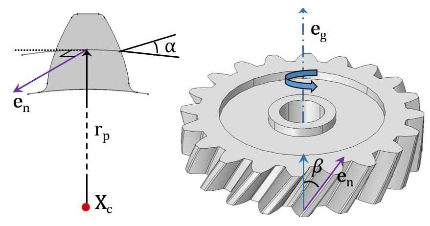
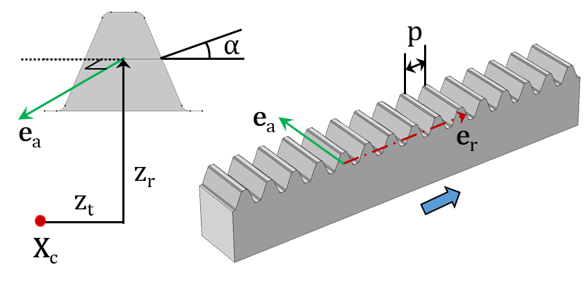
Schematic of a Helical Gear (left) and Spur Rack (right), depicting various gear parameters.
Gears are always used in pairs, which creates a need for a pair feature in COMSOL Multiphysics that connects two gears that satisfy the compatibility criteria. The following modeling nodes are available for connecting various types of gears:
- Gear Pair
- Rack and Pinion
- Worm and Wheel
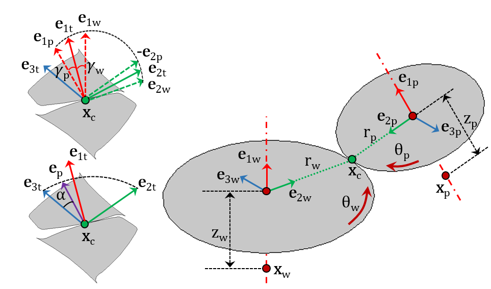
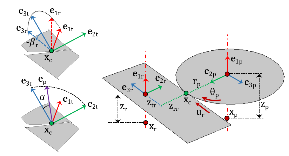
Schematic of a Gear Pair (left) and Rack and Pinion (right), depicting various coordinate systems and other important parameters.
An ideal gear pair is both rigid and frictionless, without any static transmission error or backlash. To make the gear pair more realistic, you can add the following effects via subnodes:
- Gear Elasticity: Defines the elastic properties of the gear mesh (i.e., mesh stiffness)
- Transmission Error: Specifies the static transmission error, which can result from geometrical errors and geometrical modifications
- Backlash: Defines the backlash in a gear pair, which impacts the dynamics of gears that are unloaded or lightly loaded
- Friction: Accounts for frictional forces that occur at the contact point
The series of images below highlight some of the gear pairs you can model with the new functionality.
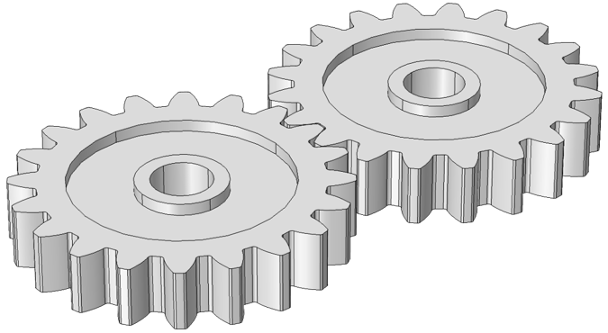
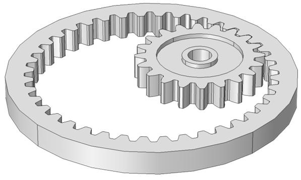
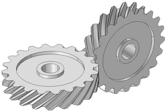
From left to right: Spur Gears (External), Spur Gears (Internal), and Helical Gears (Cross).
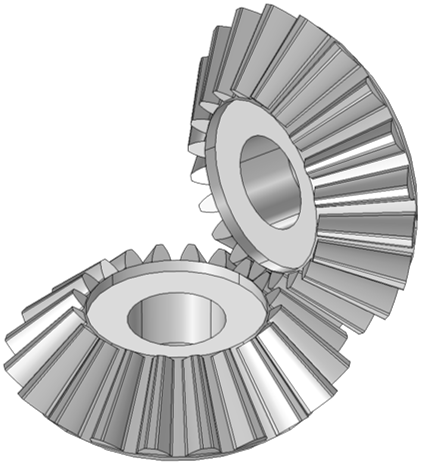
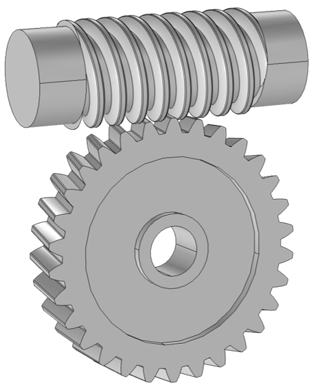
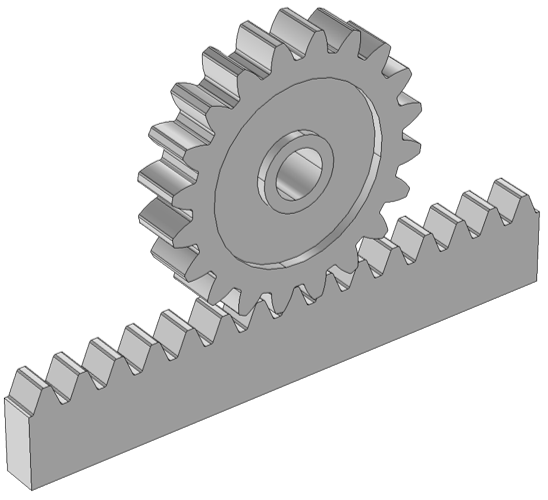
From left to right: Bevel Gears, Worm and Wheel, and Rack and Pinion.
In addition to this functionality, new parameterized gear geometry parts are also available. These gear parts are available for 2D and 3D models, with the option to customize the gear tooth and gear blank shape via input parameters. You can use these parts to build a range of items, from an individual gear to a pair of gears.
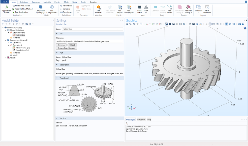
A helical gear geometry created with new gear parts included in the Parts Library.
You learn more about these upgrades in the Multibody Dynamics Module on the COMSOL Multiphysics version 5.2a Release Highlights page.
Tutorials Demonstrate a Range of Gear Modeling Applications
To showcase the new gear modeling capabilities, we’ve introduced several new tutorial models, each highlighting a different application.
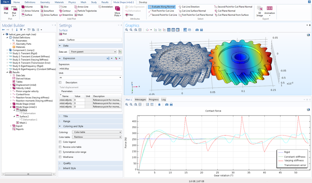
Take the vibrations in a compound gear train tutorial model, for instance. In this case, we use spur gears, which are mounted on rigid shafts, to model the gear train. By performing a transient analysis, we can study the dynamics of not only the gears but also the vibrations within the elastic housing. The gear mesh stiffness is also calculated as a function of gear rotation via a parametric analysis.
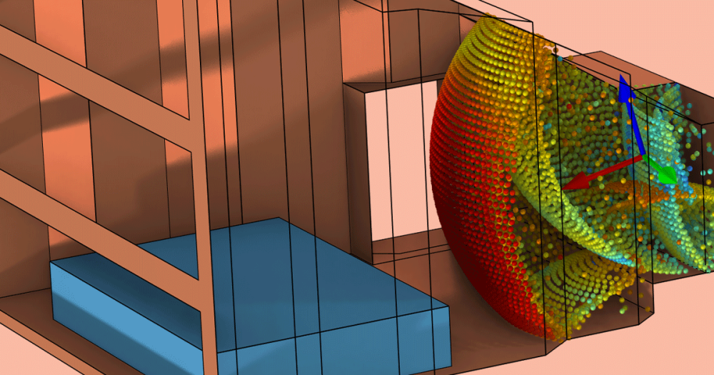
Normal acceleration in the elastic housing due to vibrations.
Von Mises stress distribution in the gears while analyzing the gear pair’s mesh stiffness.
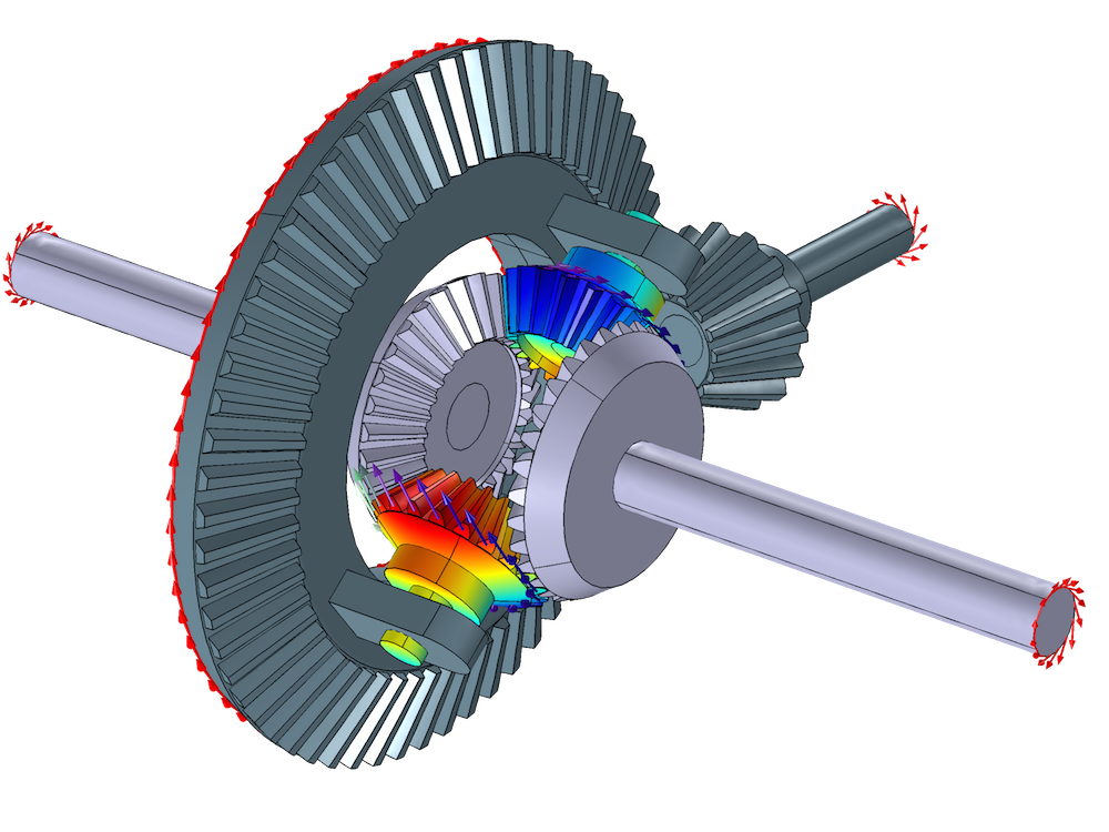
Our differential gear mechanism example, meanwhile, models a differential gear that is used within automobiles. With a differential gear, the outer drive wheel can rotate faster than the inner drive wheel — a necessary capability for a car to turn. Here, we compute the spider gears’ motion for two cases: when a car moves along a straight and a curved path. In both scenarios, the velocity magnitude of the components and the wheels’ angular velocity are calculated.
Differential gear mechanism that enables two of the vehicle’s axles to rotate at different speeds.
Also included in the mix is a tutorial model that computes the forces and moments that occur on bevel gears, as well as a tutorial that analyzes the dynamics behind helical gears. Both of these examples are highlighted below.
Bevel gear motion as an incremental rotation is prescribed.
Helical pair eigenfrequency analysis.
Concluding Thoughts on Gear Modeling
Modeling gears, a common element in mechanical devices, is now easy with new features and functionality available in the Multibody Dynamics Module. You have the ability to model various types of gears as well as include advanced effects, from the flexibility of shafts and backlash to gear mesh stiffness and damping. You can easily couple these gear dynamics with other physics to further extend the scope of your simulation analyses. The fatigue analysis of a gear tooth or the acoustic analysis of radiated noise from a gearbox are just some relevant examples.
Stay tuned for additional blog posts relating to gear modeling, where we’ll share more details on additions to the Parts Library, implementing features, and case studies. In the meantime, contact us for a software evaluation or browse the resources highlighted below.
Learn More About COMSOL Multiphysics® Version 5.2a and Modeling Gears
- Visit the COMSOL Multiphysics version 5.2a Release Highlights page to learn more about the new gear modeling features and functionality as well as additional upgrades
- Read another blog post that discusses the modeling of gears: “Modeling Magnetic Gears in COMSOL Multiphysics“


Comments (5)
ayad ahmed
June 16, 2019I want to know the meaning of the following letter of equation of multibody dynamics 0=NABLA (FS)T+FV
F=I+nabla U
thanks
Pawan Soami
June 17, 2019Dear Ahmed,
This is the equation of motion for an elastic body in stationary study.Ddifferent terms of this equation are as follows:
LHS is zero as there are no inertial terms
F – Deformation gradient tensor
S – Second Piola-Kirchhoff stress tensor
T – Transpose operation
FV – Volume force
U – Deformation vector
I – Identity matrix
You can refer Structural Mechanics Module user guide for more details.
Best regards,
Pawan Soami
Junaid Ali
February 25, 2021This article does not talk about Spiral Bevel Gears. Can we model Spiral Bevel Gears in MBD?
Pawan Soami
March 2, 2021 COMSOL EmployeeDear Junaid,
We don’t have built-in node for modeling spiral bevel gears in MBD yet. Having said that, there can be ways to model the same though. Please contact support@comsol.com for more details.
Best regards,
Pawan Soami
Omran Abdallah
October 10, 2021Hello Sir,
Is it possible to introduce cracks on the teeth of the gears using COMSOL? meaning, is there a built-in feature to add cracks on the teeth?
Thanks