Analyzing Electromagnetic Modes of Integrated Busbars Implemented as Printed Circuit Boards (PCB)
This report addresses design of a PCB intended for use as a busbar integrated with multiple DC-link (rail) capacitors in a high power inverter. The geometry and current ratings are typical of a 50 kW unit operating at 60kHz in an intermittent mode.
First, circuit aspects are analyzed. The key points are that a) the rail capacitors, Cr, currents are rich in high harmonics; b) there may be resonances between Cr’s and parasitic inductances, especially on high harmonics; c) the fundamental frequency is doubled.
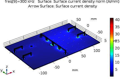
Field simulations are called for to study current sharing between Cr’s and current distribution on the board. The analysis is done in frequency domain with AC/DC module. We assume that the DC input is not on the PCB, which means that only Cr’s currents flow through PCB.
FEA is challenging, mainly because of the huge aspect ratio of the order of 1000:1. This problem can be partially circumvented capitalizing on the fact that the conductors are much thinner than the rest of the geometric entities. With Transient Boundary Conditions (TBC) and Impedance Boundary Conditions (IBC), conductors’ bulk is not modeled; only surface currents flow. Cr’s are modeled as geometrically small Lumped Elements (LE), total 8 pieces, placed between two copper layers, as pure capacitances or series LC’s. (Film capacitors usually used as DC-link possess considerable parasitic inductance.) Capacitive LEs were also modeled in volume, mimicking real parts, to include their implicit parasitic inductance. Both options showed similar results although physically the problem was posed differently. With this approach, convergence was good, and simulation time was short. Benchmarking simulations were performed both in 2D and 3D on simplified models to determine simulations accuracy. They showed that losses are typically underestimated by units to tens of percent compared to full volume simulations, depending on the ratio of the layer thickness to skin depth.
PCB simulations in a wide range of frequencies allowed visualization and quantification of Cr’s currents, proving existence of resonances at certain frequencies. However, at 120kHz, current sharing is fair. Copper losses are
Download
- pokryvailo_poster.pdf - 0.62MB
- pokryvailo_paper.pdf - 0.57MB
- pokryvailo_abstract.pdf - 0.02MB