

When an electronic device overheats, it risks starting a fire. Cooling components, such as heat sinks, are designed to prevent this, but can’t always keep up with advancing technology. Simulation offers a solution by illustrating how well various heat sink designs conduct heat and how adding elements like manifold microchannels (MMC) improves performance. Today, we’ll explore how an MMC heat sink operates with simulation.
Preventing Damage to Electronics
As laptops are designed to be thinner, faster, and lighter with every generation, the potential for them to overheat rises. Cramming more components into a smaller space means that cooling components must dissipate more heat while using less room. If the laptop produces more heat than the thermal management system can handle, the laptop poses a fire hazard. An efficient cooling system reduces this risk and prevents damage.
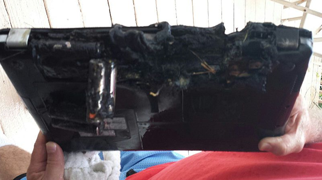
A laptop after it overheated and caught fire. Image by PumpkinSky — PumpkinSky Family. Licensed under CC BY-SA 3.0, via Wikimedia Commons.
One of the most common ways to alleviate heat is with a heat sink. As mentioned in an earlier blog post, these cooling systems are either active or passive. Active heat sinks incorporate a fan and are smaller than their counterparts. The inclusion of microchannels compensates for their smaller surface area and aids heat dissipation. These traditional microchannel (TMC) heat sinks are effective, yet they undergo large pressure drops and temperature variations.
Adding manifolds to the TMC heat sink overcomes these obstacles. They lie perpendicular to the microchannels, acting as flow dividers for the cooling air and forming numerous inlets and outlets. Manifold microchannel (MMC) heat sinks offer less thermal resistance and a greater surface area to transfer heat to this air. Including manifolds will improve the performance significantly and reduce temperature variations, which makes them more stable when integrated into an electronic device. You can use simulation to determine the optimal number and placement of manifolds.
Modeling Manifold Microchannel Heat Sinks in COMSOL Multiphysics
Although MMC heat sinks dissipate heat efficiently, producing them comes with some challenges. For one, the optimal geometric parameters and flow conditions depend on the fan’s blowing power. The width of the microchannels, inlets, outlets, and manifolds may need to be adjusted so that the heat sink reaches its best performance. Second, contact surface properties affect the thermal resistance of the cooling component. Both increasing surface roughness and low contact pressure results in higher thermal resistance. Since we want the least amount of thermal resistance possible, we need to optimize these properties for an efficient MMC heat sink.
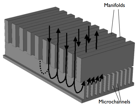
A manifold microchannel heat sink, showing inlet and outlet flow.
Measuring all of these functions in such a small device requires precise calculations and, usually, multiple design iterations. Simulation provides accurate information without the expense of manufacturing a prototype for each design change. COMSOL Multiphysics enables you to easily test the geometry of different heat sink elements so that you can find the design dimensions that provide the best air flow rate and least resistance.
Analyzing How Manifolds Affect Temperature and Velocity
You can take advantage of symmetry with the MMC heat sink and only simulate a section of the device, which consists of the three domains:
- Ceramic electronic component
- Air
- Aluminum heat sink
We find the temperature field for all three domains and the coupled flow field for the air with the Conjugate Heat Transfer interface.
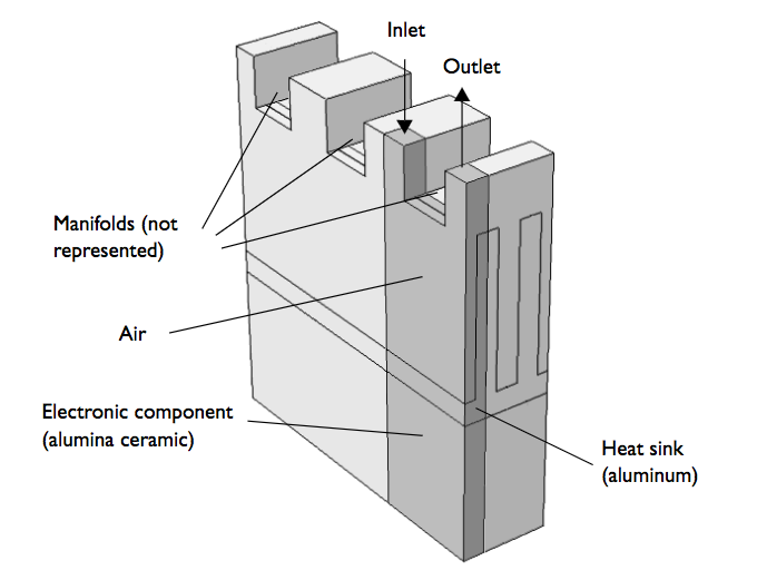
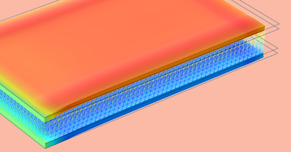
A simulated section of an MMC heat sink on an electronic component.
Next, we set boundary conditions for air velocity and thermal contact. For this example, say that the laminar inflow velocity is 0.85 m/s and the air temperature is 22°C. Another boundary condition that must be set is the thermal contact between the aluminum heat sink and the ceramic electronic component. The aim is to eliminate as much thermal resistance as possible, so we need to effectively model the contact between the two domains. While the pieces lay flat against each other, there are small surface defects that we need to account for by one of two methods. The first method requires a dense mesh to simulate the geometry of the rough surfaces. Alternatively, describing the thermal contact as nonideal makes more practical sense and accomplishes the same goal.


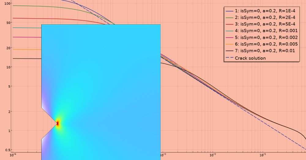
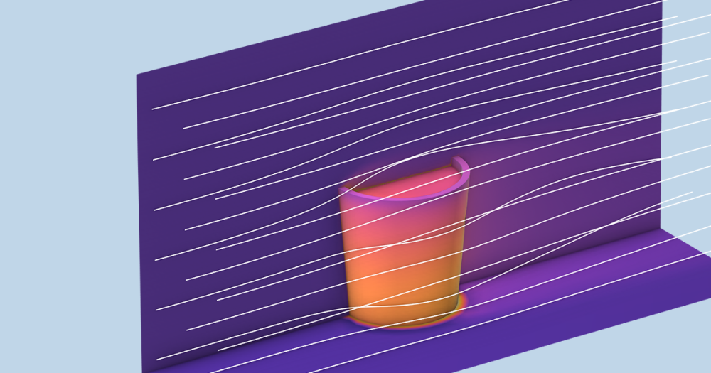
Left: Simulation results show the air flow patterns and velocity. Right: The microchannel’s resulting temperature.
The plots above show the resulting air flow patterns and velocity in addition to the temperature profile. The air flow speed increases upon exiting the outlet due to the increase in temperature. The temperature jumps by about 0.7 K at the thermal contact point due to light contact pressure. The resulting contact conductance creates a rate of approximately 8900 W/(m2·K).
With heat transfer analysis software, we can evaluate whether the MMC heat sink’s transfer abilities surpass the heat generated by the electronic component. Through the simulation results, we know that this MMC heat sink design is effective because it transfers a large amount of heat away from the device. Heat sinks that prevent devices from overheating not only benefit laptops, but can help to boost the performance of other electronic devices as well.
Learn More About Heat Sink Simulation
- Model it yourself: Download the Thermal Modeling of a Microchannel Heat Sink tutorial
- Read more blog posts on heat transfer simulation:

Comments (0)