
Microwave filters can help prevent unwanted frequency components in the output of a microwave transmitter design. However, when the microwave system experiences thermal drift, it can be difficult to achieve high-frequency stability in the filters. To address this issue and improve filter designs, system engineers need to predict the change of the passband frequency caused by thermal expansion. As we’ll see today, one way to achieve this is with multiphysics modeling.
Improving the Design of Microwave Transmitters
When designing a microwave transmitter, system engineers must ensure that there are no undesirable frequencies in its output. A common solution for this is to use a microwave filter, which is often placed between the transmitter’s antenna and nonlinear power amplifier. This amplifier generates harmonics that engineers can eliminate by applying one or more narrow passband filters on the output.
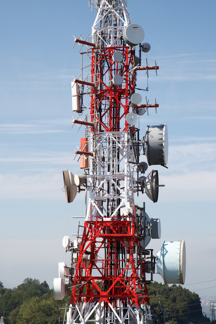
A microwave transmitter tower. Image by Tom Page — Own work. Licensed under CC BY-SA 2.0, via Flickr Creative Commons.
This solution is not without its own challenges. When a transmitter is exposed to high-power loads and harsh environmental conditions — like being in a cellular base station exposed to extreme desert heat — thermal drift can occur.

Being subjected to harsh environments, like the desert heat, can cause thermal drift in microwave transmitters. Image licensed under CC BY 4.0, via ESO/C. Malin.
Thermal expansion of the structure can distort the frequency response of filters in microwave systems. Therefore, to obtain reliable filter designs, we must not only perform an accurate electromagnetics analysis, but also study the structural deformation caused by the temperature rise. As today’s example demonstrates, we can accomplish this by using the RF Module and Structural Mechanics Module with the COMSOL Multiphysics® software.
Modeling Thermal Effects in a Microwave Filter
Let’s start by taking a look at our model, which contains a cylindrical post inside a copper box that is covered in a thin silver layer to help reduce losses. The electromagnetic cavity between the post and box is closed and filled with air. Although real filters tend to contain multiple cascaded cavities, our model focuses on one cell.
To help us compare how different designs affect the filter’s performance, we created two variations of this model:
- A design that only uses copper
- A design that uses copper for the box and steel for the post
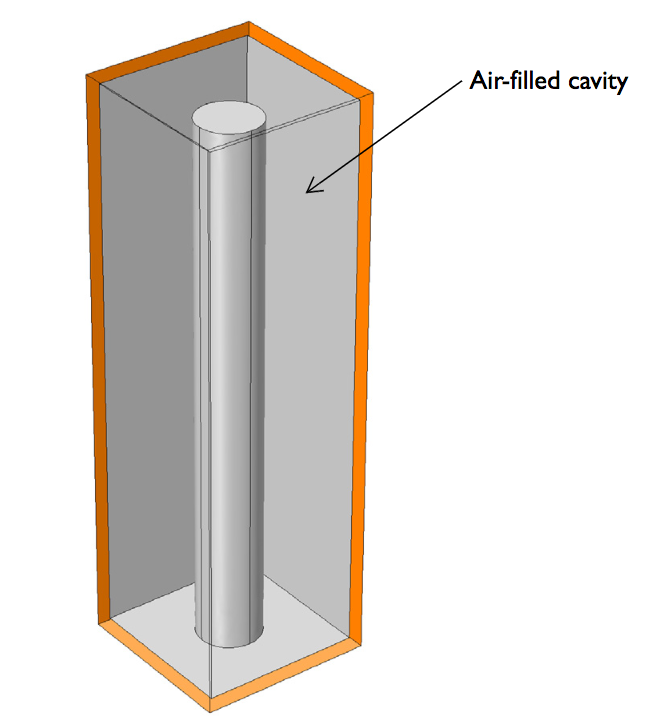
The geometry of the microwave cavity filter.
When the cavity walls experience a uniform temperature increase due to factors like external heating and power dissipation in the surrounding electronics, thermal expansion and the related eigenfrequency shift occur. Here, we model the thermal expansion using the Solid Mechanics interface in the Structural Mechanics Module. The thermal expansion causes the filter’s geometry to distort, which we account for with the Deformed Geometry interface. The resulting distorted shape is used for an electromagnetics analysis.
As for the eigenfrequency analysis of the microwave cavity, we turn to the 3D Electromagnetic Waves, Frequency Domain interface in the RF Module. Next, let’s review the results of these studies.
Studying How Thermal Drift Affects Microwave Filters
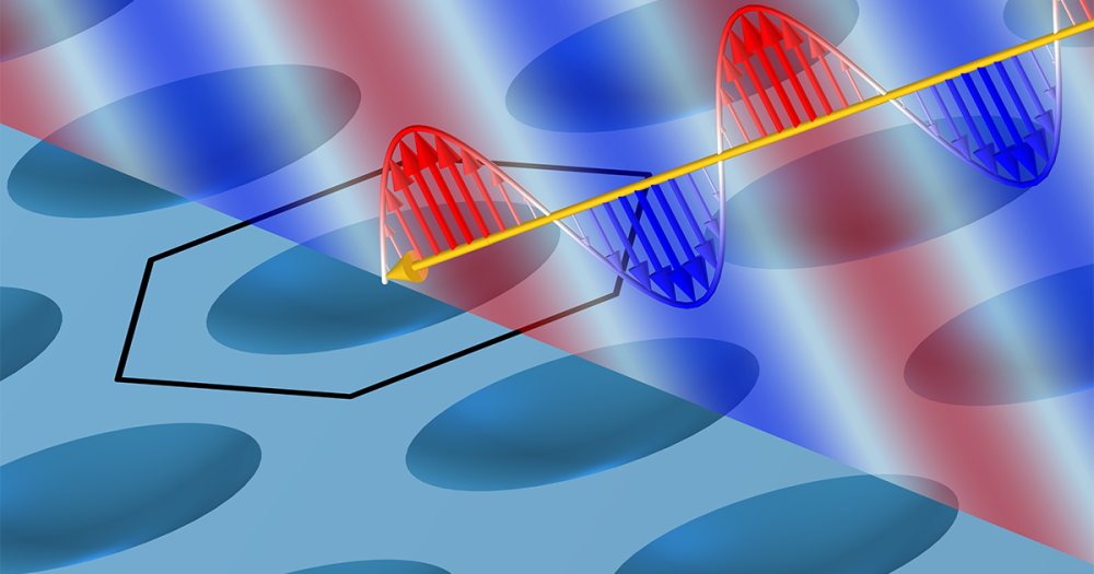
We use the design of the copper filter to calculate the filter’s thermal expansion and perform an electromagnetic resonance mode analysis. With this analysis, we can find the lowest eigenfrequency of the filter and the post’s normal quarter-wave resonance. Looking at our results, we spot a strong capacitive coupling between the post’s top and the box’s adjacent face.


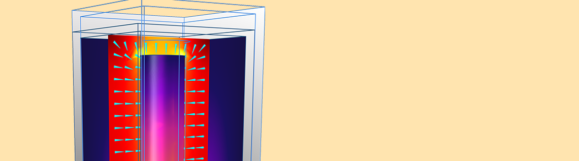
Left: The thermal expansion when the temperature is 100°C more than the reference temperature. Right: An electromagnetic mode analysis depicting both the fundamental mode’s surface current patterns and the electric field.
Moving on, we repeat these structural and electromagnetics analyses for different operating temperatures and use the resulting data to plot the eigenfrequency vs. temperature curve. With this, we compare the designs of the filter with copper only and both copper and steel.
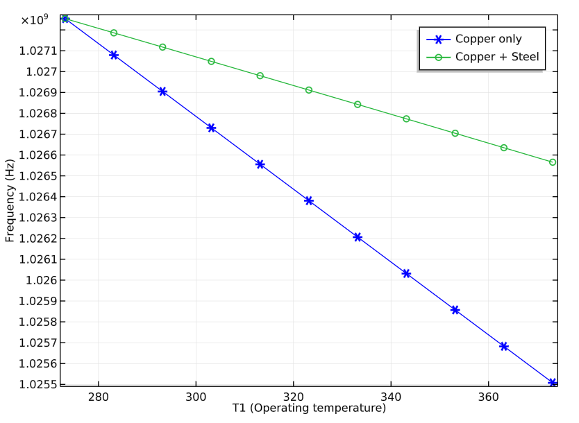
The eigenfrequency vs. temperature curve for the designs of the copper filter and copper-steel filter.
The results indicate that the filter using both copper and steel is the better of the two design variations. This is because its two materials have different coefficients of thermal expansion and as a result, the capacitive coupling is reduced between the post’s top and the box’s adjacent face. The capacitive coupling greatly influences the resonance frequency and can combat the effect of increasing the overall cavity size when reduced.
Further, in the copper-steel filter design, we can compensate for the majority of the thermal drift by applying a temperature-driven adjustment to the distance between the end of the cylinder and the box.
Learn More About RF Simulation in COMSOL Multiphysics®
- Read other blog posts on using the RF Module:
- Watch an archived webinar on simulating RF and microwave heating


Comments (0)