
The main design goal for a loudspeaker array is to achieve wider sound coverage than a single speaker could provide. At the same time, the radiation pattern of the array must be indistinguishable from that of a single speaker. One method for producing radially distributed sound for multiple loudspeakers is with a Bessel panel. By analyzing a benchmark model of a Bessel panel system, engineers can optimize the design of loudspeaker arrays and other acoustics systems.
Bessel Functions and the Bessel Panel
In the 19th century, a German mathematician and astronomer named Friedrich Bessel, in his studies of planetary motion, used functions that had previously been used by Bernoulli, Euler, and others. These functions, which later became known as the Bessel functions, have a wide variety of applications within the field of acoustics. For instance, Bessel functions can be used to analyze the vibrations of a circular membrane, like the radial part of a drum’s modes of vibration. These functions can also show how an infinite array of loudspeakers with their own input signals can act as one loudspeaker with the same pattern of sound distribution.
In 1983, Philips patented a type of loudspeaker system based on the idea behind Bessel functions. Known as the Bessel panel, it offered a way to arrange standard, low-cost speakers to produce radially distributed sound. Besides being inexpensive, the speakers could be assembled without active or passive components.
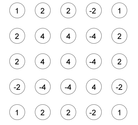
The assembly and input to each speaker in a typical Bessel panel combination.
Although they are not commonly in use today, Bessel panels are a good starting point for analyzing sound distribution in loudspeakers. This benchmark model of a Bessel panel demonstrates that using the COMSOL Multiphysics® software and add-on Acoustics Module is a valid method for this type of near- and far-field acoustics analysis.
Modeling a Bessel Panel with a Hybrid BEM-FEM Approach
The model geometry for the Bessel panel consists of two neighboring loudspeakers that are 0.5 m apart, with a box extending 0.2 m around the array of points.
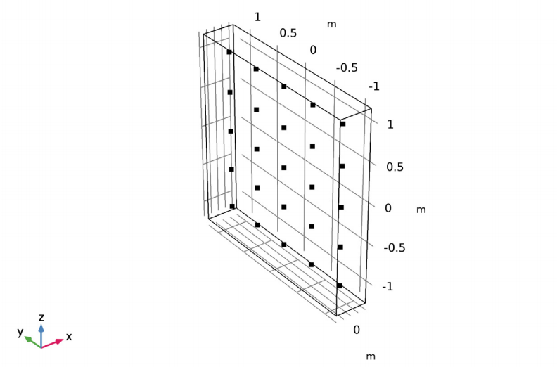
A schematic of the Bessel panel model geometry.
Five Bessel panels arranged in the same pattern approximate a purely radial sound field. Each panel consists of five loudspeakers placed in a row with equal distance between them. For this system, the input (voltage and current) is weighted by the factors 1, 2, 2, −2, and 1 so that we have a homogeneous polar far-field distribution.
To solve for the sound radiation from the idealized speaker panel, we can take advantage of both the boundary element method (BEM) and finite element method (FEM) using a hybrid approach, available as of version 5.3a of the COMSOL Multiphysics software. FEM is used to model the acoustics around the point sources and BEM models the rest of the radiation problem. We can use the built-in BEM-FEM multiphysics coupling between the following interfaces to determine the pressure outside of the computational domain:
- Pressure Acoustics, Frequency Domain
- Pressure Acoustics, Boundary Elements
These interfaces solve the Helmholtz equation and the simulation results are compared with the analytical solution, which is set up as a variable.
Coupling BEM and FEM and using BEM for the exterior domain of the model presents certain advantages. For instance, there is no need to mimic the open domain using radiation conditions or perfectly matched layers (PMLs), which you would have to do if you were only using FEM. In fact, in this instance, BEM acts like an idealized radiation condition combined with the far field, which avoids the use of the Far-Field Calculation feature explicitly.
Validating the Simulation Results
First, let’s look at the results for the near-field distribution, specifically the pressure distribution and sound pressure level distribution at 200 Hz. Observe the pressure distribution in a slice close to the loudspeaker plane. We can see that the sound field is not very homogeneous in the immediate vicinity of the sources. This relates to directivity. If you’re right in front of a speaker, its frequency response will seem flat to you, whereas someone sitting to the side will hear more balanced frequencies.
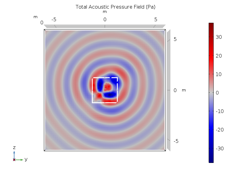
Pressure distribution at 200 Hz. The slice is parallel with the yz-plane and situated at x = 0.2 m.
Next, look at the sound pressure level distribution around this same sliced area, x = 0 m. An array, like a Bessel panel, offers greater sound pressure level distribution because the pressure overlaps depending on the distance and spacing between the speakers. We could change the combination and arrangement of Bessel panels to adjust the sound concentration and direction of distribution.
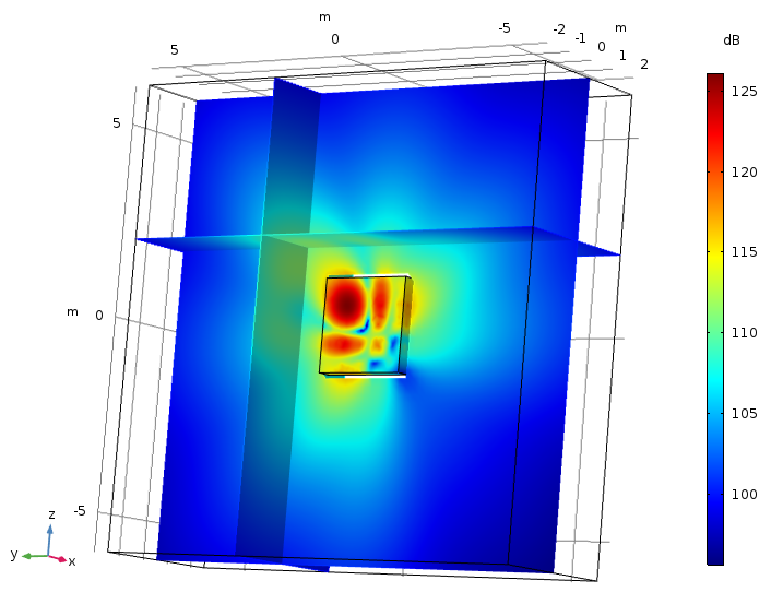
Sound pressure level distribution at 200 Hz. The slice is parallel with the yz-plane and situated at x = 0 m.
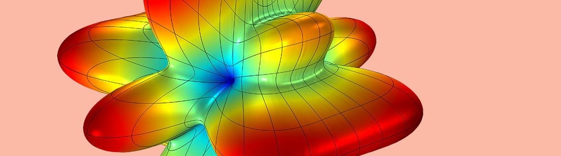
Next, let’s take a look at the far-field distribution 100 m from the speakers. Because the scale limits are equal to the global extremes of the sound pressure level, we can see below that the sound pressure level in any two given directions doesn’t differ by more than 3 dB — meaning that the sound quality and distribution is similar no matter the location of the subject.
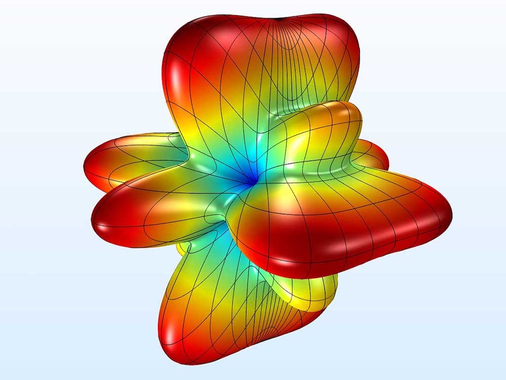
Sound pressure level (dB) at a distance of 100 m from speakers, represented as a 3D far-field polar plot.
We can examine the angular sound distribution at a 100-m distance from the loudspeakers by comparing the computed solution (blue) with the analytical solution (green) in the plot below. The plot shows the computed far-field pressure at the radial distance vs. the polar angle in the positive xz-plane. The computed solution and the analytical solution are very close, and we could even increase the accuracy slightly by refining the mesh.
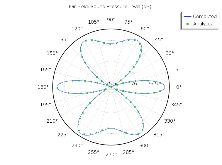
Sound pressure level (dB) at a radial distance of 100 m in the xz-plane as a function of the polar angle from the xy-plane.
The COMSOL® software can generate reliable results that match an acoustics benchmark model. By combining BEM and FEM, you can perform robust analyses of sound distribution acoustics designs.
Next Steps
Try the Bessel panel model: Click the button below to go to the Application Gallery, where you can download a step-by-step tutorial and the accompanying MPH-file.
- Browse these blog posts about designing loudspeakers:
- Learn more about using BEM and FEM in acoustics modeling:

Comments (1)
René Christensen
July 31, 2018Nice. Is there actually any need for the FEM domain, other than having the monopoles predefined?